

SCI(UART) 포스팅을 끝내지 않고 SPI로 넘어왔다. 해야 할 일이 있어서 넘어왔다. TI DSP에서 SPI를 사용할 수 있는 방법은 크게 두 가지다. 기본적으로 제공하는 SPI를 사용하는 방법과 McBSP를 사용하는 방법이다. McBSP는 SPI 정리가 다 되면 포스팅할 예정이다.
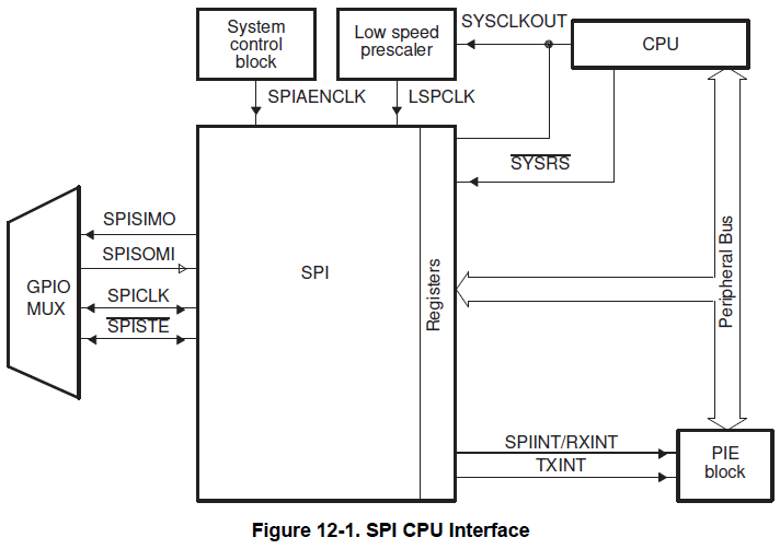
TI에서 제공하는 SPI도 다른 MCU의 SPI와 큰 차이는 없다. Blcok diagram을 보면 딱히 어렵지 않다.
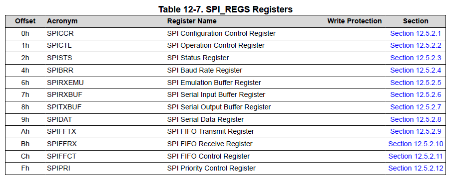
SPI 관련 레지스터는 총 12개다.
SPI의 이론적인 내용은 아래 포스팅 참고!
SPI란?, SPI 통신, SPI 통신 이론, CPOL, CPHA, Clock Polarity, Clock Phase
SPI(Serial Peripheral Interface)는 IC를 제어하는 직렬 통신이다. I2C와 함께 가장 많이 사용되는 통신 프로토콜로 보통 센서, 메모리 등의 IC를 보면 I2C와 공통으로 지원하는 경우가 많다. 용어 정리 MOSI,
vuzwa.tistory.com
본 포스팅에서는 TI에서 제공하는 예제를 기반으로 Flash Memory인 AT45DB041D를 제어해보도록 하겠다.
Flash Memory 보드는 waveshare에서 판매하는것을 사용했다. 엘레파츠에서 판매한다. 관련 자료는 아래 링크 참고
https://www.waveshare.com/wiki/AT45DBXX_DataFlash_Board
AT45DBXX DataFlash Board - Waveshare Wiki
Introduction A tool for DataFLash with SPI interface, AT45DBxx on board Resources FAQ Support If you require technical support, please go to the Support page and open a ticket.
www.waveshare.com
SPI-A를 사용하고, 연결은 아래와같이 연결
| TMS320F28069M | AD45DB041D |
| VCC(3.3v) | VCC |
| GND | GND |
| GPIO16(MOSI) | MOSI |
| GPIO17(MISO) | MISO |
| GPIO18(CLK) | CLK |
| GPIO19(CS, SPISTEA) | \CS |
AT45DBXX보드의 WP, RESET은 기본적으로 3.3V(High)에 연결되어 있다. GPIO로 제어하고 싶다면 연결되어 있는 저항을 제거하고 GPIO에 연결하면 된다.
SPI 관련 레지스터는 크게 SPI 설정 레지스터와 FIFO 레지스터로 구분할수 있다.(이건 내 개인적인 의견) 우선 SPI 설정 레지스터 먼저 확인해보자.
static void spi_register_init(void)
{
    // SPI Configuration Control Register(SPICCR)
    //Enabling Sequence Step 1
    SpiaRegs.SPICCR.bit.SPISWRESET = 0;
    //Disable Loopback Mode;
    SpiaRegs.SPICCR.bit.SPILBK = 0;


    // SPI Baud Rate Register
    // 0, 1, 2 SPI Baud Rate = LSPCLK / 4
    // 3 Tto 127 SPI Baud Rate = LSPCLK / (SPIBRR + 1)
    //Step 2, Set Baud Rate to 900kHz
    SpiaRegs.SPIBRR = 0x0000;


    // SPI Operation Control(SPICTL)
    //Enabling Master Mode on microcontroller
    SpiaRegs.SPICTL.bit.MASTER_SLAVE = 1;
    // Transmit Enable
    SpiaRegs.SPICTL.bit.TALK = 1;
    //As Described on page 849 of Manual, in order to trigger SPIINT w/o FIFO, this bit needs to be set to 0.
    SpiaRegs.SPIFFTX.bit.SPIFFENA = 0;

    // CPOL, CPHA, data bit
    //(databit - 1), Transmit 8 bits per clock cycle.
    SpiaRegs.SPICCR.bit.SPICHAR = 8-1;
    //"Clock Phase And Polarity". Both Phase and Polarity need to be set to 1 in order to initiate communication.
    SpiaRegs.SPICCR.bit.CLKPOLARITY = 0;
    SpiaRegs.SPICTL.bit.CLK_PHASE = 1;

    //Step 3, Enable SPI
    SpiaRegs.SPICCR.bit.SPISWRESET = 1;
    SpiaRegs.SPIPRI.bit.FREE = 1;
}
레지스터 설정은 c2000 SDK에서 device_support\f2806x\examples\c28\spi_loopback 예제와 데이터시트를데이터 시트를 참고했다. 여기서 중요한 부분은 baudrate 설정과 CLK_PHASE, CLKPOLARITY 설정인데 baudrate 설정은 데이터 시트를 보면 어렵지 않게 설정할 수 있고, CLK_PHASE, CLK_POLARITY 설정은 아래 포스팅을 참고하면 된다.
SPI란?, SPI 통신, SPI 통신 이론, CPOL, CPHA, Clock Polarity, Clock Phase
SPI(Serial Peripheral Interface)는 IC를 제어하는 직렬 통신이다. I2C와 함께 가장 많이 사용되는 통신 프로토콜로 보통 센서, 메모리 등의 IC를 보면 I2C와 공통으로 지원하는 경우가 많다. 용어 정리 MOSI,
vuzwa.tistory.com
다음은 FIFO 설정이다.
static void spi_fifo_init(void)
{
	SpiaRegs.SPIFFTX.bit.SPIRST = 1;
	SpiaRegs.SPIFFTX.bit.SPIFFENA = 1;
	SpiaRegs.SPIFFTX.bit.TXFIFO = 1;

	SpiaRegs.SPIFFTX.bit.TXFFST = 0x00;
/*	0 = Transmit FIFO as empty
	1 = Transmit FIFO has 1 word
	2 = Transmit FIFO has 2 word
	3 = Transmit FIFO has 3 word
	4 = Transmit FIFO has 4 word, witch is the maximum
	1F = reserved	*/

	SpiaRegs.SPIFFTX.bit.TXFFINT = 0;
	SpiaRegs.SPIFFTX.bit.TXFFINTCLR = 1;
	SpiaRegs.SPIFFTX.bit.TXFFINT = 0;

	SpiaRegs.SPIFFTX.bit.TXFFIL = 0x00;
/*	0h (R/W) = A TX FIFO interrupt request is generated when there are no words remaining in the TX buffer.
	1h (R/W) = A TX FIFO interrupt request is generated when there is 1	word or no words remaining in the TX buffer.
	2h (R/W) = A TX FIFO interrupt request is generated when there is 2	words or fewer remaining in the TX buffer.
	3h (R/W) = A TX FIFO interrupt request is generated when there are 3 words or fewer remaining in the TX buffer.
	4h (R/W) = A TX FIFO interrupt request is generated when there are 4 words or fewer remaining in the TX buffer.
	1Fh (R/W) = Reserved.		*/


	SpiaRegs.SPIFFRX.bit.RXFFOVF = 0;
	SpiaRegs.SPIFFRX.bit.RXFFOVFCLR = 0;
	SpiaRegs.SPIFFRX.bit.RXFIFORESET = 1;
	SpiaRegs.SPIFFRX.bit.RXFFST = 0;
/*	0h (R/W) = Receive FIFO is empty.
	1h (R/W) = Receive FIFO has 1 word.
	2h (R/W) = Receive FIFO has 2 words.
	3h (R/W) = Receive FIFO has 3 words.
	4h (R/W) = Receive FIFO has 4 words, which is the maximum.
	1Fh (R/W) = Reserved.	*/

	SpiaRegs.SPIFFRX.bit.RXFFINT = 0;
	SpiaRegs.SPIFFRX.bit.RXFFINTCLR = 1;
	SpiaRegs.SPIFFRX.bit.RXFFIENA = 0;
	SpiaRegs.SPIFFRX.bit.RXFFIL = 0x04;
/* 	0h (R/W) = A RX FIFO interrupt request is generated when there is 0 or more words in the RX buffer.
	1h (R/W) = A RX FIFO interrupt request is generated when there are 1 or more words in the RX buffer.
	2h (R/W) = A RX FIFO interrupt request is generated when there are 2 or more words in the RX buffer.
	3h (R/W) = A RX FIFO interrupt request is generated when there are 3 or more words in the RX buffer.
	4h (R/W) = A RX FIFO interrupt request is generated when there are 4 words in the RX buffer.
	1Fh (R/W) = Reserved. */

    SpiaRegs.SPIFFCT.all=0x0;
}
주석이 거의 대부분이다. 아래 코드는 데이터를 보내고 받는 코드
Uint16 Tcnt=0;
Uint8 spi_rdata[20]={0, };  // received data

void spi_xmit(Uint8 a)
{
    SpiaRegs.SPITXBUF=a;
	while(SpiaRegs.SPIFFRX.bit.RXFFST != 1)	{

	}

	spi_rdata[Tcnt++] = SpiaRegs.SPIRXBUF;
}

void spi(void)
{
	GpioDataRegs.GPACLEAR.bit.GPIO19 = 1;

	spi_xmit(0x9F00); // transmit data
	spi_xmit(0x0000); // transmit data
	spi_xmit(0x0000); // transmit data
	spi_xmit(0x0000); // transmit data
	spi_xmit(0x0000); // transmit data
	spi_xmit(0x0000); // transmit data

	GpioDataRegs.GPASET.bit.GPIO19 = 1;
}
AT45DB041D 데이터 시트대로 0x9F를 보내 IC의 Manufacturer and Device ID Information을 읽어오는 코드다. 실제 동작을 시켜보면,


잘 동작한다. 자료는 정리되는 대로 git에 올릴 계획이다.
혹시 틀린 부분이나 질문있으면 댓글 부탁드려요 ~~
- 끝 -
'Hardware&Firmware > Texas Instrument(TI)' 카테고리의 다른 글
| [TMS320F28069M] SPI(Serial Peripheral Interface)-2(with AT45DB041, Flash Memory) (0) | 2022.09.09 |
|---|---|
| [TMS320F28069M] SCI(Serial Communication Interface)-2 (0) | 2022.08.30 |
| [TMS320F28069M] SCI(Serial Communication Interface)-1 (0) | 2022.08.10 |
| [TMS320F28069M] GPIO 컨트롤, GPIO 설정, DSP GPIO 제어하기-2 (0) | 2022.07.10 |
| [TMS320F28069M] TI DSP EALLOW? (0) | 2022.07.05 |